- 您现在的位置:买卖IC网 > Sheet目录1222 > ISL54222IRUEVAL1Z (Intersil)EVAL BOARD 1 FOR ISL54222IRU
�� �
�
�Application� Note� 1450�
�DC� POWER�
�SUPPLY�
�DC� POWER�
�SUPPLY�
�+�
�+1.8V�
�-�
�+�
�+5V�
�-�
�LOGIC� CONTROL�
�COMPUTER�
�USB� PORT�
�SEL�
�J4�
�VDD�
�GND�
�J1�
�J2�
�OE�
�J3�
�VBUSCH1�
�J8�
�JP4�
�USB�
�USB� TO� HOST�
�TO�
�DEVICE� 1�
�J5�
�JP1�
�U1�
�JP2�
�JP5�
�J6�
�USB�
�USB� HIGH-SPEED� DEVICE� 1�
�TO�
�DEVICE� 2�
�JP3�
�J7�
�USB� HIGH-SPEED� DEVICE� 2�
�VBUSCH2�
�J9�
�ISL54222AEVAL1Z� EVALUATION� BOARD�
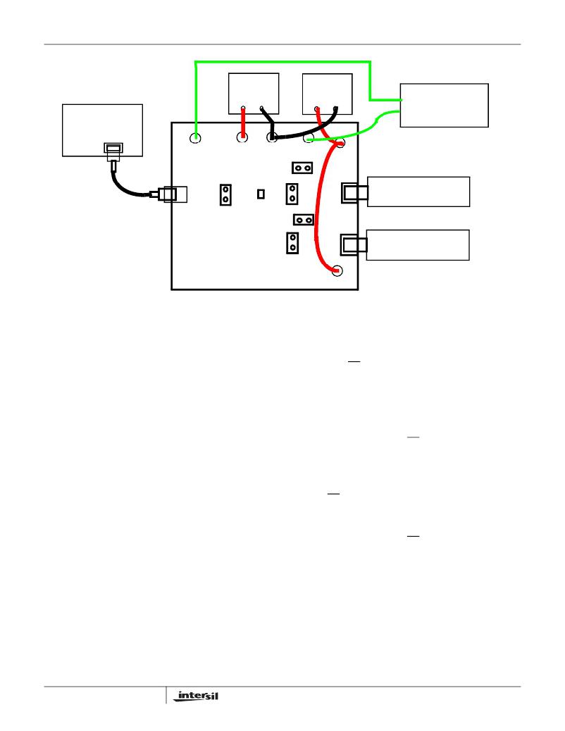
�NOTE:� DISCONNECT� THE� +5V� POWER� SUPPLY� CONNECTED� TO� J8� AND� J9� WHEN� POWERING� THROUGH� HOST� CONTROLLER� BUS.�
�FIGURE� 2.� BASIC� EVALUATION� TEST� SETUP� BLOCK� DIAGRAM�
�Using� The� Board� (Refer� to� Figure� 2)�
�Lab� Equipment�
�The� equipment,� external� supplies� and� signal� sources�
�needed� to� operate� the� board� are� listed� in� the� following:�
�1.� +1.8V� to� +3.3V� DC� Power� Supply�
�2.� +5V� DC� Power� Supply�
�3.� Two� High-Speed� USB� device� (i.e.� USB� memory� stick,�
�MP3� Player,� etc.)�
�4.� Computer� with� 2.0� High-Speed� USB� port�
�5.� Standard� USB� Cable�
�6.� Logic� Controller�
�Initial� Board� Setup� Procedure�
�1.� Attach� the� main� evaluation� board� to� a� DC� power� supply�
�at� J1� (V� DD� )� and� J2� (GND).� Positive� terminal� at� J1� and�
�negative� terminal� at� J2.� The� supply� should� be� capable� of�
�delivering� 1.8V� to� 3.3V� and� 100μA� of� current.� Set� the�
�supply� voltage� to� 1.8V.�
�2.� Connect� a� DC� power� supply� at� J8� (VBUSHCH1)� and� J9�
�(VBUSCH2).� Positive� terminal� at� J8� and� J9� and� negative�
�terminal� at� J2� (GND).� The� supply� should� be� capable� of�
�delivering� 5V� and� 100mA� of� current.� Set� the� supply�
�voltage� to� 5V.� This� supply� will� provide� 5V� at� the� V� BUS� pin�
�of� the� USB� “A”� type� connectors,� J6� and� J7.�
�3.� Connect� one� high-speed� USB� device� at� USB� connector�
�J6� and� the� other� high-speed� USB� device� at� USB�
�connector� J7.� These� connectors� are� located� on� the� right�
�side� of� the� evaluation� board.�
�4�
�4.� Remove� jumpers� JP4� and� JP5.�
�5.� Drive� the� OE� control� pin� HIGH� to� open� all� switches� of� the�
�ISL54222A� IC.�
�6.� Connect� USB� cable� from� host� (PC� computer)� to� the� USB�
�“B”� type� receptacle,� J5� (USB� TO� HOST).�
�High-Speed� Channel� 1� Operation�
�1.� Apply� a� logic� LOW� to� the� SEL� pin.�
�2.� Apply� a� logic� LOW� to� the� OE� pin.�
�3.� You� should� now� be� able� to� send� and� receive� data�
�between� the� computer� and� the� USB� device� 1� connected�
�at� J6.�
�4.� To� disconnect� the� USB� device� 1� from� the� computer� take�
�the� OE� pin� HIGH.�
�High-Speed� Channel� 2� Operation�
�1.� Apply� a� logic� HIGH� to� the� SEL� pin.�
�2.� Apply� a� logic� LOW� to� the� OE� pin.�
�3.� You� should� now� be� able� to� send� and� receive� data�
�between� the� computer� and� USB� device� 2� connected� at�
�J7.�
�Test� Points�
�The� board� has� various� test� points� for� ease� of� connecting�
�probes� to� make� measurements.� The� test� points� available� are�
�described� in� Table� 2.�
�AN1450.1�
�July� 24,� 2009�
�发布紧急采购,3分钟左右您将得到回复。
相关PDF资料
ISL54406EVAL1Z
EVALUATION BOARD FOR ISL54406
ISL55110EVAL1Z
EVALUATION BOARD FOR ISL55110
ISL55111EVAL1Z
EVALUATION BOARD FOR ISL55111
ISL5629EVAL1
EVALUATION PLATFORM FOR ISL5629
ISL58125CRZ-EVAL
EVAL BOARD FOR ISL58125CRZ
ISL58214CRZ-EVAL
EVAL BOARD FOR ISL58214
ISL6115AEVAL1Z
EVAL BOARD 1 FOR ISL6115A
ISL6115EVAL1Z
EVAL BOARD ISL6115
相关代理商/技术参数
ISL54222IRUZ-T
制造商:INTERSIL 制造商全称:Intersil Corporation 功能描述:High-Speed USB 2.0 (480Mbps) Multiplexer
ISL54222IUZ
制造商:INTERSIL 制造商全称:Intersil Corporation 功能描述:High-Speed USB 2.0 (480Mbps) Multiplexer
ISL54222IUZ-T
制造商:INTERSIL 制造商全称:Intersil Corporation 功能描述:High-Speed USB 2.0 (480Mbps) Multiplexer
ISL54223
制造商:INTERSIL 制造商全称:Intersil Corporation 功能描述:High-Speed USB 2.0 (480Mbps) Multiplexer
ISL54223_09
制造商:INTERSIL 制造商全称:Intersil Corporation 功能描述:High-Speed USB 2.0 (480Mbps) Multiplexer
ISL54223IRUZ-T
制造商:INTERSIL 制造商全称:Intersil Corporation 功能描述:High-Speed USB 2.0 (480Mbps) Multiplexer
ISL54224
制造商:INTERSIL 制造商全称:Intersil Corporation 功能描述:High-Speed USB 2.0 (480Mbps) Multiplexer with Overvoltage Protection (OVP) and Overvoltage Indicator Output
ISL54224IRTZ
功能描述:IC MULTIPLEXER DUAL 2:1 10TDFN RoHS:是 类别:集成电路 (IC) >> 接口 - 模拟开关,多路复用器,多路分解器 系列:- 其它有关文件:STG4159 View All Specifications 标准包装:5,000 系列:- 功能:开关 电路:1 x SPDT 导通状态电阻:300 毫欧 电压电源:双电源 电压 - 电源,单路/双路(±):±1.65 V ~ 4.8 V 电流 - 电源:50nA 工作温度:-40°C ~ 85°C 安装类型:表面贴装 封装/外壳:7-WFBGA,FCBGA 供应商设备封装:7-覆晶 包装:带卷 (TR)